<< Home
1. Creating a Character Rig using Maya 2008 software.
2. Binding the Character Rig to the game character’s mesh.
3. Creating an animated walk Cycle
4. Creating textures for the game model
5. Creating an environment, baking shadows & illumination to a texture map.
6. Exporting game characters to a file format for a game engine
7. Importing characters into a 3-D game engine.
8. Controlling characters using data from input device.
9. Adding environment to the game.
|
1. Animating the skeleton as it is in it's current state would prove to be a difficult task. Select the “leftankle” joint and use the “Move Tool” to move it forward. Notice how the calf bone stretches unrealistically. We can fix this by using the “IK Handle Tool.”
Press “Ctrl” + “Z” on your keyboard at the same time to reset the bone back to it's original position.
2. Go to the “top menu” and select “Skeleton”. In the dropdown menu you will see an item called “IK Handle Tool”. Click on it and again you will see your arrow pointer turn into a crosshair icon  . .
3. Now click once on the “leftHip” in the “perspective” viewport. The leg joints should highlight.
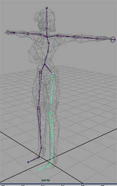
4. Next, click on the ankle joint. This will tell the IK tool where to “end” our IK “chain”. After this is done, it creates an” IK handle” and a visual link from the IK handle to the beginning of the chain (leftHip). We can use the IK handle to move the foot around without the calf bone stretching. While the IK Handle is selected and we're in “Move” mod, drag the IK handle around the viewport to see what it does. Nice.
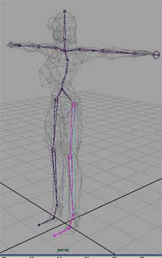 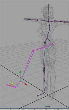
5. Press “Ctrl + Z” on your keyboard to reset the ikHandle's position and repeat the process for the right leg, keeping in mind that the order in which you select the bones is very important. While using the IK handle tool, first select the “rightHip” (the beginning of our chain) then select the “rightAnkle” (the end of our IK chain).|
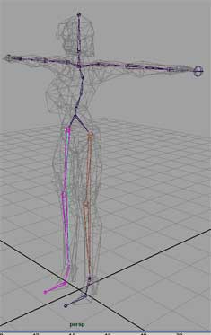
6. Switch to the “top” view and do the same thing for both arms, using the shoulders as the beginning of the chains and the wrists as the ends of the chains.

7. Using the Outline panel, rename the IK handles according to which joint each handle is nearest to. For example the IK handle near the left ankle can be renamed to “ikLeftAnkle”
8. IK handles work well for general motion, but what if we want to rotate a wrist or ankle? Currently, the rotation of this skeletons foot and wrist joints cannot be controlled because these IK Handles “only” control the position of the joints, “not rotation”. We can solve this by using NURBS circle primitives as control objects. Why NURBS circle primitives? Because they are easy to see, select and manipulate without obstructing any views of your model mesh.
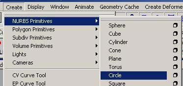
Goto the “top-menu” and click on “Create”. In the “Create” drop-down menu, place your mouse over “NURBS primitives” and then click on “Circle”.
9. Click and Drag your cursor inside of the “top” viewport to create a NURBS circle that’s slightly wider than the leg of the character. If you accidently de-select the sphere before creating it, you can just select it again and modify it’s size with the “Scale Tool” located in the left-hand toolbar.
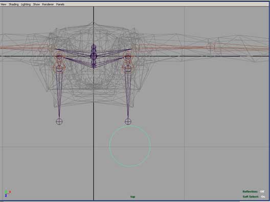
10. While the NURBS circle is selected, click on the “Move Tool” (left toolbar)
11. In the “perspective” viewport, select the circle (if not selected) and hold down the “V” key on the keyboard. His enables “vertex snapping” mode.
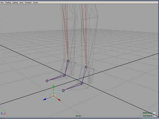
12. Drag the NURBS circle over the leftAnkle joint, while continuing to hold the “V” key. When you see the center of the NURBS circle “snap” into place, let go of the mouse button and the “V” key.
13. Now that the NURBS circle is now in place, let’s “Freeze” it’s transformations, by clicking on “Modify” on the top-menu and then “Freeze Transformations” from the drop-down menu that appears. This sets the current XYZ positions & rotations of the object to “0”. This means that no matter where we move or how we rotate this controller object, we can always reset it back to this original ”frozen” position by manually setting its position or rotation values back to “0”.
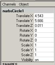 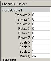
14. While this NURBS circle is selected, press “Ctrl + D” on the keyboard to duplicate it. You will notice a copy of this NURBS circle appears in the “Outliner” panel. Make sure that this copy is currently selected.
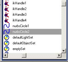
15. Select the “Move tool” once again and hold “V” on your keyboard while moving the newly duplicated NURBS circle to the “leftAngle” joint.
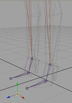 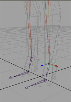
16. Once it snaps into place, “freeze” it’s transformations and repeat the duplication/placement steps for both wrist joints while remembering to rotate the Nurbs circles 90 degrees on the Z axis “before freezing” the transformations. Rotating the circles 90 degrees keeps the circle from inersecting the arm, making the arm controllers easier to select and see.
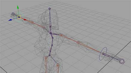
17. After all 4 controls are in place, rename each control according to each joint that each controller is closest to (just as was done with the iK handles) For example, the controller near the left ankle would be renamed to “contLeftAnkle”.
18. Finally all there is left is for us to do is parent the ik handles and joints, that we wish to rotate and move, to the controls.
19. Let’s start with the ikHandles. We only wish to translate these, so let’s parent them to the “control” objects we created by using the “Parent” constraint. Make sure that "Animation" is selecte as the current menu set, by using the drop-down menu located in the top left-hand corner, directly above the viewports  . .
20. Using the outliner, select the “ikLeftAnkle” first, because this will be the object that we want the controller to translate. Then, while holding the “shift” key, select the “contLeftAnkle” control, because it will act as a “parent” to the “leftAnkle”, controlling its “translation”.
Note: the shift key allows you to select multiple objects at once. Always select the “child” object (or object to be controlled) first when creating constraints.
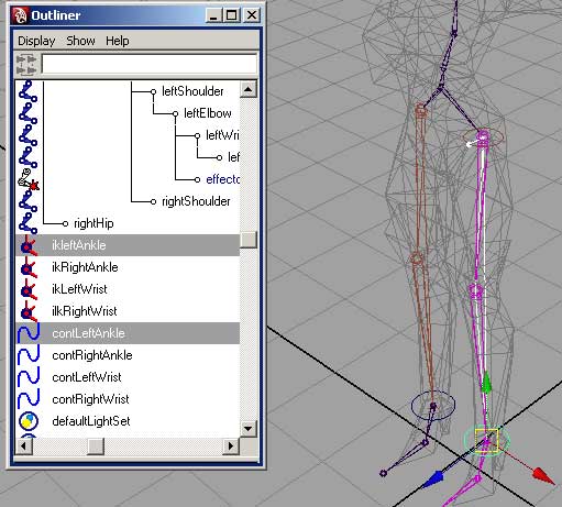
21. While these two items are selected, select “Constraints” from the top-menu and from the drop-down that appears, select “Parent constraint. All transformations of the “ikLeftHandle” are now controlled by the “contLeftAnkle” control.
If you use the “Move Tool” to move the “contLeftAnkle” controler around, you can see that it now controls the translation of “ikLeftAnkle”. IK handles however do not control rotation, even when controlled by a parent constraint. At this point, we will use “Orient constraint” to enable “contLeftAnkle” to rotate the “leftAnkle” joint directly. Pres “Ctrl +Z” to place the “contLeftAnkle” back into it’s “frozen” position.
22. Instead of selecting the ikController first, select the actual “leftAnkle” joint. While holding the “shift” key, click on the “contLeftAnkle” control. We now want the controler to control the leftAnkle joint’s “orientation”, this is why we are going to now use the “Orient” constraint.
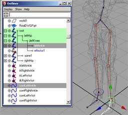
23. From the top-menu, choose “Constrain” and from the drop-down menu click on “Orient Constraint Options” .
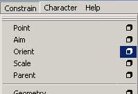
24. When the “options” window for this tool appears, insure that the “Maintain Offset” option is checked. If, not then click on the check box to enable it. Once enabled, this allows the controller to constrain the joint’s angle without it’s current rotational values being affected.

25. Click “Add” which is located at the bottom-left of the window. The “Orient constraint” is now created.
26. Rotate “contleftAnkle” using the “Rotate Tool” to see how the “leftAnkle” joint reacts. The left foot joints should now rotate around the “leftAnkle” joint. Press “Ctrl + Z” until “contLeftAnkle” Is back in it’s original “frozen” position.
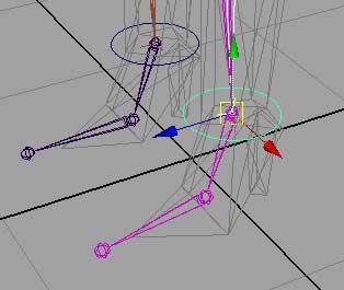
27. Now repeat the process for the “contRightAnkle” and the two wrist controls.
28. Finally, we will create our final control for the head. Switch to the “top” viewport and create a new NURBS circle (Top Menu -> Create -> NURBS Primives -> Circle)
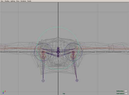
28. Select he “Move Tool” (left-hand toolbar)
29. Change to the “side” viewport and while holding down the “V” key to “snap” the NURBS circle in place over the “head” joint.
 
30. Once in place, “Freeze” the NURBS circle transformations and use “Outliner” to change it’s name to “contHead”.

 
31. We only need to use the controller to “rotate” the head, so instead of creating both a “Parent” and “Orient” constraint for this joint, we “only” need to create an “Orient” constraint to control the joints “rotation”. In Outliner, select the “head” joint, and while holding the “shift” key, select the “contHead” controller.
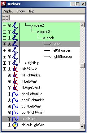
32. Select “Constrain” from the top-menu and from the drop-down menu that appears, click on “Orient Constraint”. The constraint is created and we can rotate our “contHead” control to see how it works. Use “Ctrl + Z” to reset the controls orientation when done.

You are now done with the rig, in the next lesson we will bind the rig to the character model and adjust it’s influence on the charcter’s mesh . Lesson 02 >> |